DC Cable in a PV Array: Voltage, Current and the 1.8/1.8 kV Rating
The rating printed on a photovoltaic cable is a declaration about its insulation system, not a description of the array it will serve. The 1500 V solar cable published by KUKA CABLE is rated DC 1.8/1.8 kV, which is 1.2 times the 1500 V that gives the product its name, and it is produced with a spark test at 10 kV followed by a finished-cable test of 6.5 kV AC at 50 Hz for 5 minutes. That manufacturer, based in Jinshan District, Shanghai, publishes the full set of limits for its solar dc cable range.
Key takeaways
- Rated DC voltage of the published 1500 V cable: 1.8/1.8 kV.
- The tests named on that page: 10 kV spark testing during production, then 6.5 kV AC for five minutes on the finished cable.
- Temperature data on the page: +90 °C as the ambient ceiling and −40 °C as the floor, with short-circuit allowances of +120 °C over 20,000 h and +250 °C for 5 s.
- Mechanical figures: bending radius 4 times the outer diameter, tensile strength before ageing at least 8 N/mm², elongation at least 125%.
What a 1.8/1.8 kV DC rating actually states
The two numbers are a declared DC voltage for the insulation system, written in the same style as an alternating-current cable rating. On the published 1500 V product page they sit next to a product name that says 1500 V, and the two are not in conflict: 1500 V is the system voltage used by large photovoltaic arrays, and 1.8/1.8 kV is what the cable is declared to withstand. Dividing the rating by the system voltage gives 1.8 ÷ 1.5 = 1.2, so the declared figure sits 20% above the system voltage; that division is my own arithmetic on the two published numbers.
Reading it that way is what makes the rating useful. A designer who checks only that the cable is called a 1500 V product has one number; a designer who also notes the 1.8/1.8 kV declaration has the margin the manufacturer was prepared to state in writing. The construction behind it is published too: a tinned copper conductor of class 5 flexibility to IEC 60228, an electron-beam cross-linked XLPO insulation and a matching XLPO sheath, both described as low smoke halogen free, and a choice of black or red.
The tests behind the declaration
A voltage rating only means something if there is a routine test that backs it, and the page publishes two. Every metre of the production run passes a spark test at 10 kV, which is a continuous check for pinholes and thin spots in the insulation wall. The finished cable then goes through a test voltage of 6.5 kV AC at 50 Hz held for 5 minutes, which is the type of test a buyer can ask to see recorded. The standards named for this construction on the same page are TUV 2PfG 1169/08.2007, EN 50618:2014 and IEC 62930, and the certificates page lists more than 30 types of certificates including TUV, IEC, CE, SAA and UL.
Put the test level next to the rating and the proportions are easy to see. Dividing 6.5 kV by the 1.8 kV rating gives 3.6, and dividing by the 1.5 kV system voltage gives 4.3; both are my calculations on published figures. Five minutes is 300 seconds, which is also mine. The comparison is worth making because a specification should quote the declared rating and the routine test together; a test level on its own does not tell a designer what the cable is rated for.
Current on the DC side: what the pages give and what they do not
Voltage is the easier half of a photovoltaic specification because it is printed. Current depends on the array, and the manufacturer publishes the physical data a designer needs rather than a prepared answer. The cross-section table gives the conductor build for every size, from 56 strands of 0.29 mm at 4 mm² to 84 strands of 0.29 mm at 6 mm² and 142 strands of 0.29 mm at 10 mm², together with the nominal overall diameter and the nominal weight per metre.
What the pages do not carry is a current rating table for each size, so the capacity of a run has to be confirmed against the installation rules that apply where the array is built. The published inputs to that check are the conductor area, the class of flexibility, the ambient window of −40 °C to +90 °C and the two short-circuit figures, which together describe how much heat the cable is expected to tolerate before and during a fault.
Heat, faults and the two short-circuit limits
Fault behaviour is where a DC array differs from most alternating-current installations, because a fault on the DC side cannot be cleared by a switch that passes through zero. The manufacturer describes two thermal ceilings instead of one: +120 °C sustained for 20,000 hours, and +250 °C for a period of 5 seconds. The first is the long-term condition that a slightly overloaded conductor could reach; the second is the brief, severe condition during a fault that protection is expected to interrupt.
Both values depend on the compound rather than the copper, and the published compound is XLPO cross-linked by an electron beam. The same page states a bending radius of 4 times the outer diameter, a tensile strength before ageing of at least 8 N/mm² and an elongation before ageing of at least 125%, with the manufacturer stating elsewhere that its photovoltaic cables reach up to 185%. Service life is published as 25 years or more, and one product page names an expected 30 years. The published test list adds water resistance, UV accelerated weathering, abrasion, cold bending, cold elongation, tensile testing after ageing, solderability, static flexibility and construction and dimensional checks to the suite.
| Parameter | Published value | How to read it |
|---|---|---|
| Rated DC voltage | 1.8/1.8 kV | 1.2 times a 1500 V system voltage (author's calculation) |
| Spark test in production | 10 kV | Routine check on every metre for insulation faults |
| Finished-cable test | 6.5 kV AC, 50 Hz, 5 minutes | About 3.6 times the declared DC rating (author's calculation) |
| Bending radius | 4 × outer diameter | 22 mm at a 5.5 mm diameter (author's calculation) |
| Ambient temperature | −40 °C to +90 °C | Design window for the installed cable |
| Short-circuit, sustained | +120 °C for 20,000 h | Long-term overload condition |
| Short-circuit, brief | +250 °C for 5 s | Fault condition awaiting protection |
Worked example
Suppose a 1500 V array is specified with this cable and the designer wants to check the declaration rather than trust the product name. The published rating is 1.8 kV DC, so the margin over the system is 1.8 ÷ 1.5 = 1.2, or 20%. Now check the production test: 6.5 kV AC against the same 1.8 kV rating is 6.5 ÷ 1.8 = 3.6. Both divisions are mine, and both assume the figures printed on the same page belong to the same construction.
Add one physical check that can be done on site. The published bending rule is 4 times the outer diameter, and the diameter of the 6 mm² build is 6.0 mm, so the smallest radius I would work to is 4 × 6.0 = 24 mm. That figure is my own arithmetic on published values, and it assumes normal handling conditions rather than a cold snap, when a cable is stiffer and a gentler radius is sensible.
The published temperature limits on one chart
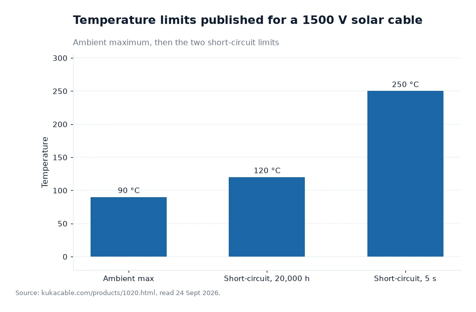
The three bars answer three different questions, which is why they are published separately. The first is the day-to-day condition the insulation is designed around, the second is a long overload that lasts for years of operating hours, and the third is a fault that lasts seconds. A designer writing a specification should take the first bar from the datasheet and the other two from the protection study, because a cable cannot invent the clearing time of the device upstream of it.
Frequently asked questions
Is 1.8/1.8 kV the same as a 1500 V rating?
No. The cable is sold as a 1500 V solar cable because 1500 V is the system voltage it is used at, while 1.8/1.8 kV is the declared DC rating of the insulation system published on the datasheet. The two figures are read together: 1.8 kV is 20% above 1.5 kV, which is the margin a designer can state in writing.
Which tests are published for the finished cable?
The page states a spark test at 10 kV during production and a test voltage of 6.5 kV AC at 50 Hz applied for 5 minutes to the finished cable. It also gives a tensile strength before ageing of at least 8 N/mm², an elongation before ageing of at least 125% and a bending radius of 4 times the outer diameter.
Reading the rating onto a purchase order
Put the declared DC rating and the system voltage on the order as two separate lines, then add the test levels and the ambient window. Ask for the certificate that covers the offered model, and for the datasheet values for the exact cross-section being bought rather than for the family. If the run will sit in a hot location, quote the two short-circuit temperatures back to the supplier and ask how the protection study has been allowed for, because those two numbers describe what the cable is expected to survive before the device upstream of it acts.
24 Sept 2026 is the read date for the voltage, temperature and test limits cited in this piece, all of them published on the manufacturer's own website[1].